Categories
Projects

Rev 2 PCB

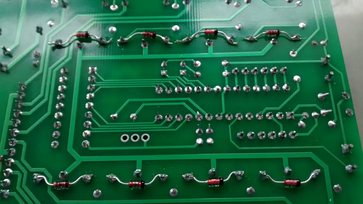
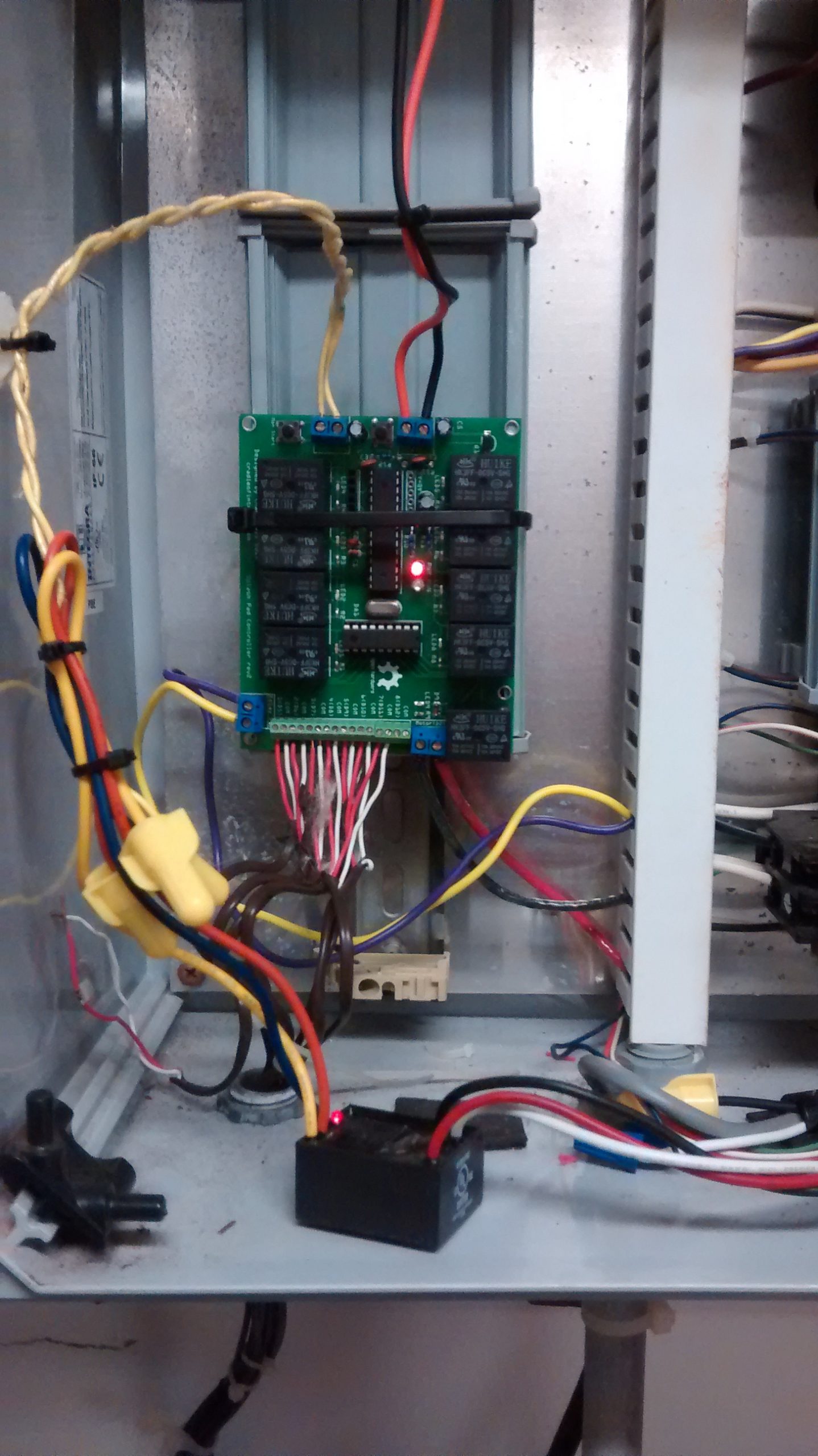
So the last PCB with the tacked on diodes finished off the 2014 season. I did have an issue at the begining of the year, but luckily that was just an isue with the 5v wall wart I was powering board with.

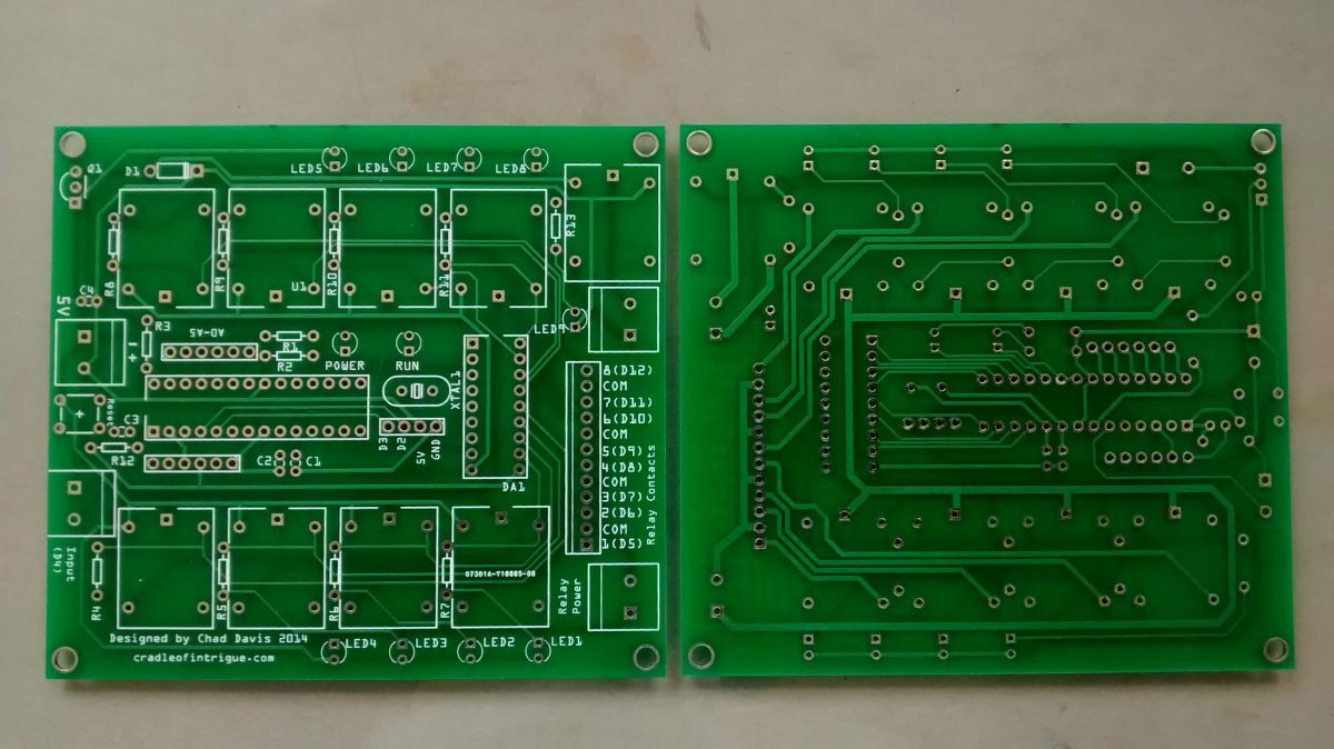
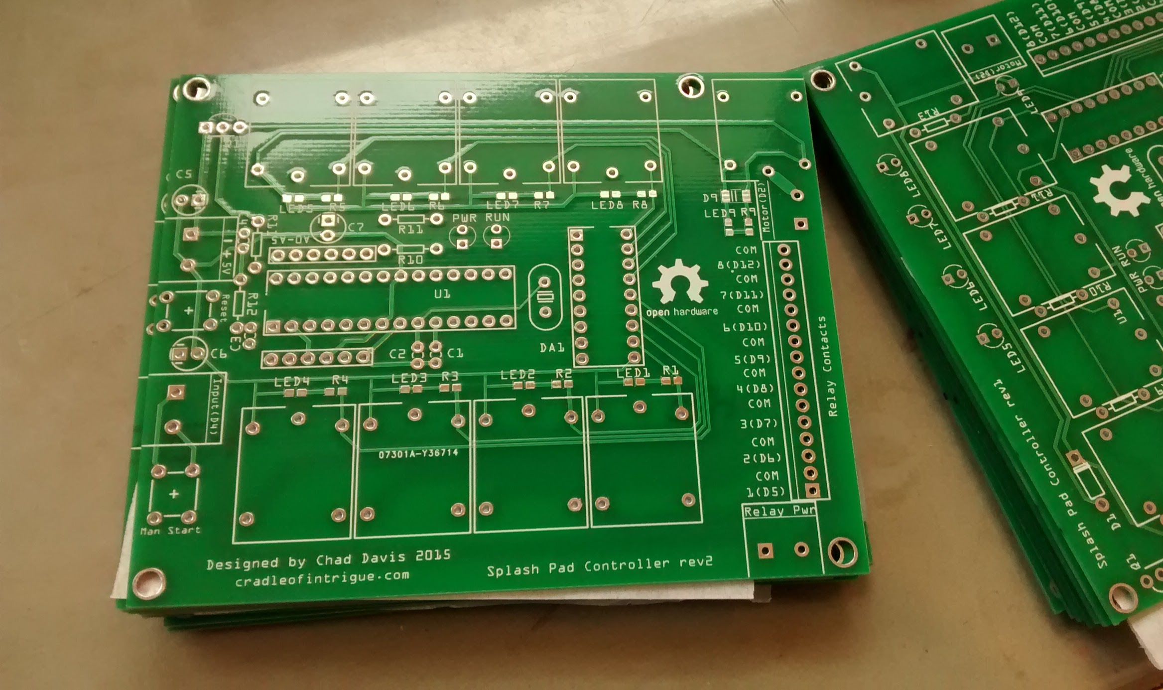
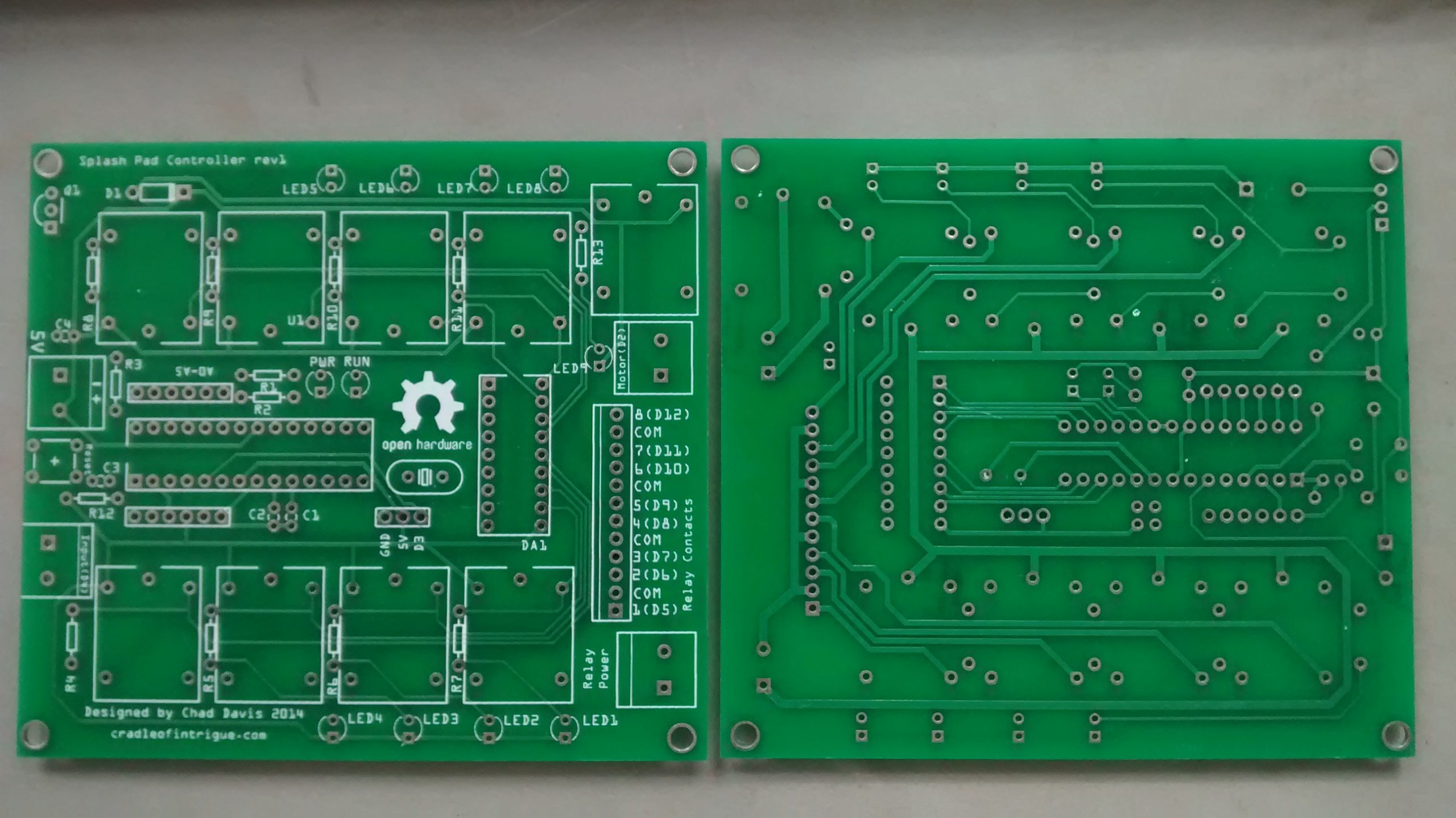
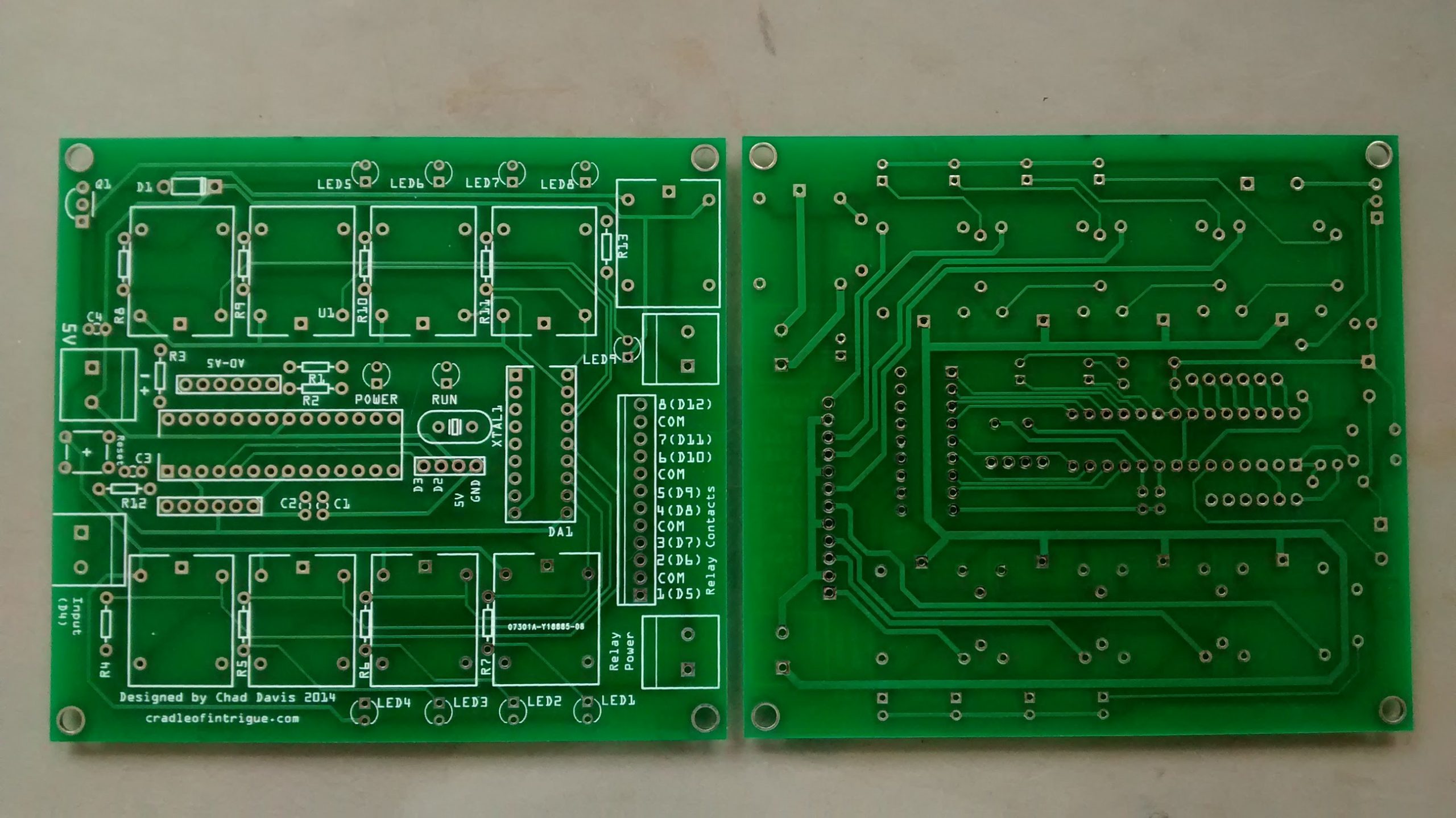
 I pretty finished next PCB design sometime toward the end of the season, but never got around to ordering it, or the new parts I needed. I kept the diodes on the back of the board between the coil pins, but used a DO-213AA package. I switched the relay indicator LEDs and paired resistors to 0603 SMD components. Which turned out to quite small. With a no-clean solder syringe they were quite easy to solder, though. I did use my stereo macroscope and it helped a lot. I found out after I ordered my PCBs from Tayda carries 0805 resistors, so any further revisions will probably switch to those. Tayda also now carries relays with the footprint I use. So, potentially they have everything but the SMD LEDs, SMD diodes, and 2.54mm pitch screw terminals.

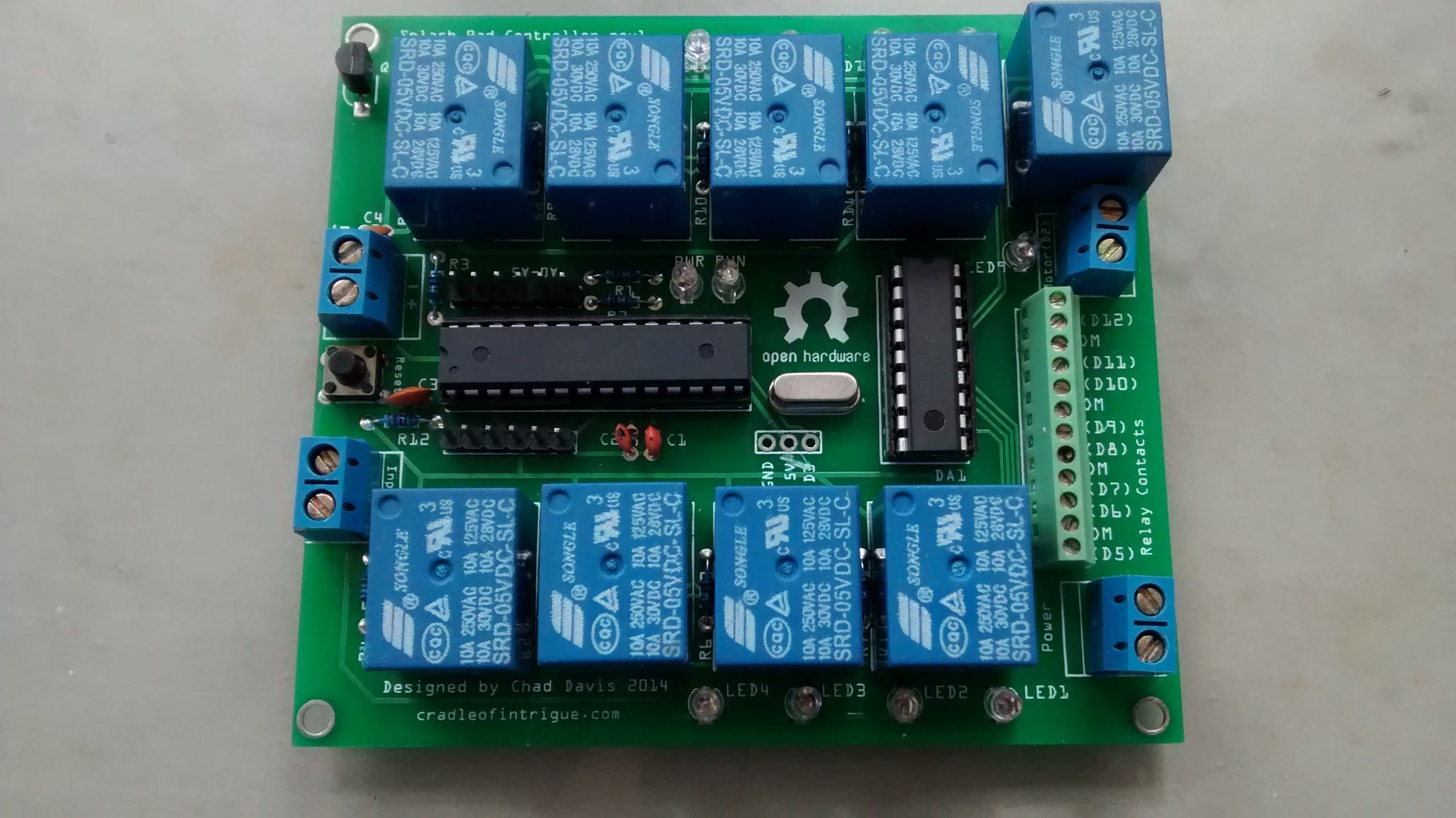
 There, of course, was one issue with the PCB I found after testing the SMD LEDs before I put anything else on the board. I accidentally put a trace between the pads for LED3. A sharp razor blade made short work of fixing that though.

As long as everything keeps working, I’m not going to do much with this for a while, but try to document it a bit and get the files in better order.

Update: I have the Fritzing file on Github
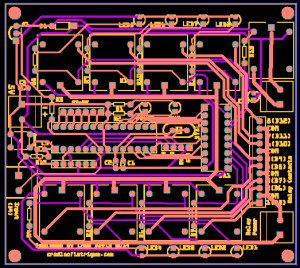
Categories
Projects

New PCBs, New Problems

The new PCBs arrived and I soldered everything on, testing as I went. I used an Uno to bit-bang the Duemilanove bootloader to the Atmega328P. ICSP programmers are pretty cheap on eBay, so I ordered one for the future. The headers below the Atmega are for a USB FDTI adapter for uploading sketches. Everything worked great on the bench with no solenoids connected– you can see where this is going.

Once I installed the board It would cycle through one or two steps of switching on/off solenoids and reset. I pulled it out and gave the board a good looking over and found a possible problem. I left some points for the extra digital pins (which was down to 1 after I realized my mistake mentioned in my last post) in case I wanted them for something in the future. When I fixed the last problem I, for some reason, decided to also connect the 5V point, from a trace that passed the VCC supply pin on the Atmega to a trace supplying the relay coil power. I cut that extra trace and it now worked better, but only for a minute or two.

The only thing I could think of was some interference from the current in the 24v solenoid circuit. I now know that interference to be called di/dt (dee eye by dee tee). When the solenoids shut off the inductance of the 24V wire creates high voltage(radio wave) that jumps to the relay coil (antenna). That spike doesn’t do good things to microprocessors.

In my sketch I had 4 of the 8 relay pins randomly selected and turned off, then four randomly selected of the 8 again. So sometimes 4 relays could be shutting off at the same time. I changed the code to select one relay that was engaged and swap it with one that was off. It actually cycled through the entire program… sometimes.

The Darlington array (ULN2803) has internal diodes, but maybe they weren’t good enough? I soldered a 1N4803 Diodes between the coil pins on each relay. The polarity is backward of the current on the board, otherwise, it would short the DC– which would be bad. But it does still short the high voltage AC from the di/dt– which is good. Success! Working as planned. It’s been running for 2 days with no issue… so far. I’ll see how it works for a while before I bother creating a new PCB design including the new diodes. Even with a third (and let’s just assume I’ll need a 4th) round of PCBs, with the components for 3 boards (2 backups), I’ll be under $200. With a price tag of $2K on the replacement computer that I had no confidence in and would still be waiting to arrive, I feel pretty good about this. I’m not a programmer and the Arduino IDE is my only exposure so far to C++, but here is the sketch that I painfully got to work.

int stepLength = 6000;//6 sec steps
int steps = 50;//50 step
//6sec * 50 = 5min
int waitState = 1;


void setup(){
  Serial.begin(9600);
  pinMode(2, OUTPUT);
  pinMode(4, INPUT_PULLUP);
  pinMode(5, OUTPUT);
  pinMode(6, OUTPUT);
  pinMode(7, OUTPUT);
  pinMode(8, OUTPUT);
  pinMode(9, OUTPUT);
  pinMode(10, OUTPUT);
  pinMode(11, OUTPUT);
  pinMode(12, OUTPUT);
  pinMode(13, OUTPUT);
  
}

void loop() {
  digitalWrite( 2, LOW);//turn off motor
  digitalWrite( 4, HIGH);//HIGH is inactive for internal pullup
  int pin = 5;
  while(pin <= 13){//turn off all solenoids and run led
   digitalWrite( pin, LOW);
   delay(100);
   pin++;
  }
  waiting(); 
}

void waiting(){
 if(waitState == 1){ 
   Serial.println("Waiting for Input...");
   waitState = 0;
 }
 if(digitalRead(4) == LOW){//wait for input
   beginSeq();
 }
}

void beginSeq(){
 digitalWrite( 4, HIGH);//HIGH is inactive
 digitalWrite(13, HIGH);//turn on run led
 startFour();//open 4 solenoids
 digitalWrite(2, HIGH);//start motor
 delay(stepLength);
 int stepNum = 2;
 while(stepNum <= steps){
   Serial.print('\n');
   Serial.print("Step ");
   Serial.print(stepNum);
   Serial.print(": ");
   swapFeature();
   delay(stepLength);
   stepNum++;
 }
 Serial.println("");
 digitalWrite(2, LOW);//stop motor
 digitalWrite(4, HIGH);//deactiveate input pin
 delay(5000);//wait 5 seconds before all the solenoids slam shut
 waitState = 1;
}

void startFour(){
 Serial.print("Step 1: ");
 int pin = 5;
 while(pin <= 12){
   digitalWrite( pin, LOW);
   pin++;
 }
 int i = 0;
 while(i  ");
 Serial.print(turnOn);
 digitalWrite(turnOn , HIGH);
 digitalWrite(turnOff , LOW);
}

int turnOffPin(){
  while(true){
   int pin = random(5,12);
   if(digitalRead(pin) == HIGH){//check that pin is on
    return pin;
   }
  }
}

int turnOnPin(){
  while(true){
   int pin = random(5,12);
   if(digitalRead(pin) == LOW){//check that pin is off
    return pin;
   }
  }
}
Categories
Projects

PCBs Arrived & Error Found

The boards look great. Itead did a great job and I got them quite a bit faster than I expected. Unfortunately, I made an error. I managed to, rather than connect to a signal pin on the Atmega, connect the circuit to open the relay intended for the motor controller to a VCC pin. There are 2 extra digital pins free that I left solder points for. I’ll be able to cut a trace and solder on a jumper wire for the time being. I fixed the error in Fritzing and after looking it over for the next couple of days, I’ll order another set of boards.

The Pro Mini I have running has needed reset a couple of times this week, but the old computer controller needed rebooted every couple of days as well. But if I get a call about the splashpad not working, with the arduino, I have no problem saying unplug and plug it back in. 2 seconds after that everything is back in operation.

Update: The controller got stuck again repeatedly. I looks like the problem was being caused by the wires for the input pin from the motion sensor relay being too close to the 24VAC solenoid wires. I re-positioned the wires and have not had an issue since.

Categories
Projects

PCBs Ordered

I played with some parts and finished a PCB design in Fritzing the last few days. I’m still waiting for some terminal connectors and relays I had to get on ebay. 10 copies of the board + shipping is going to run under $30. I opted for the cheap shipping so it’ll be a few weeks before they are manufactured and make it here from China. The Pro Mini I have running things at the moments is working fine, so I’m not in a rush and I tend to prefer keeping my money rather than getting something faster anyway.