
The control panel on the lid was the obvious place to mount the LCD. I had already removed the potentiometer for laser intensity and the momentary switch for test firing the laser– both of those functions were present in the Arduino controller. I had thought about keeping the ammeter and the laser power switch, but they were in the way and really didn’t provide anything too useful. So they’re gone now, leaving only the power switch.
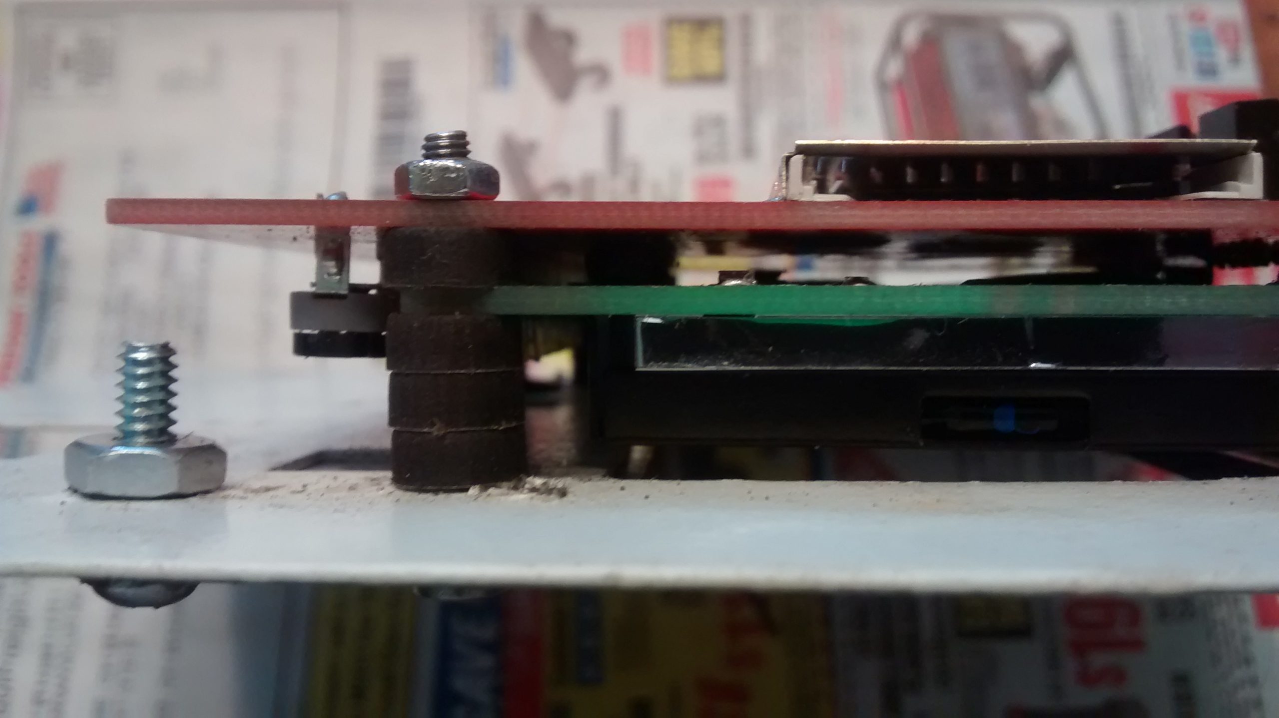
The only other issue was the distance from the panel to the Arduino at the bottom of the case. So I found som
The control panel on the lid was the obvious place to mount the LCD. I had already removed the potentiometer for laser intensity and the momentary switch for test firing the laser– both of those functions were present in the Arduino controller. I had thought about keeping the ammeter and the laser power switch, but they were in the way and really didn’t provide anything too useful. So they’re gone now, leaving only the power switch.
e 70cm IDC cables on eBay.
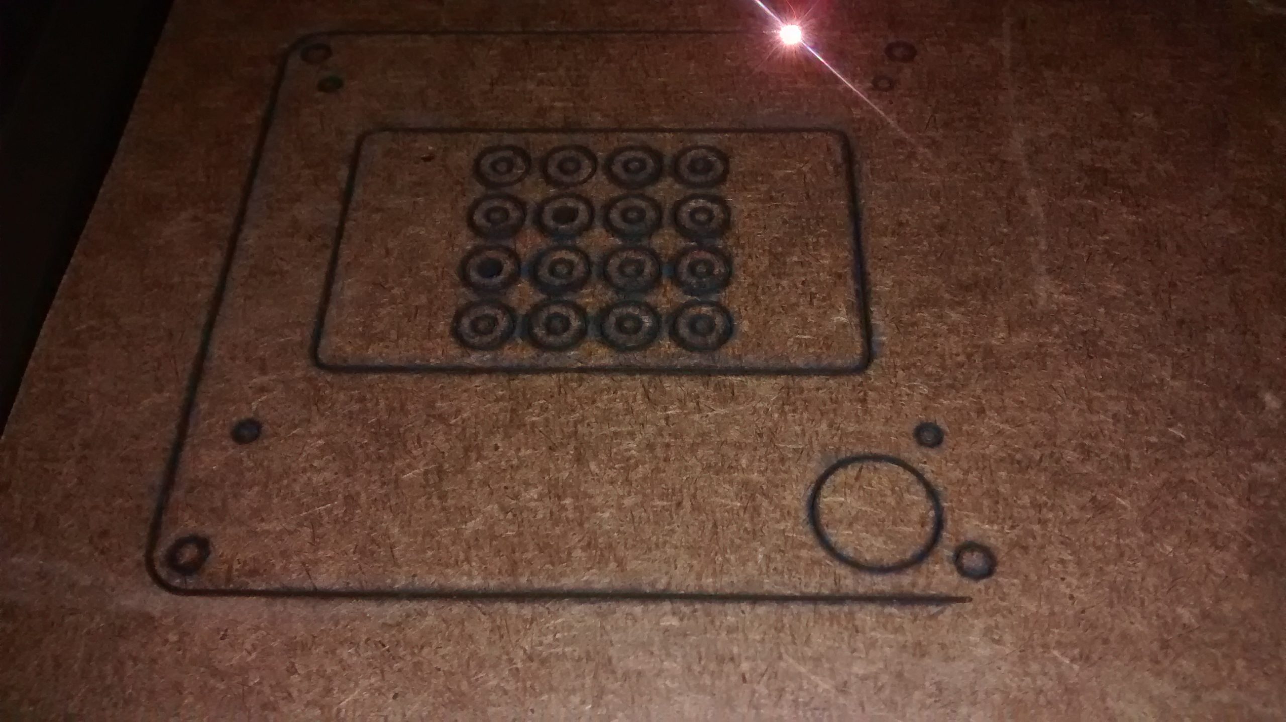
In Inkscape I drew a mounting panel as well as some spacer washers that would hold the LCD and cover all of the holes left by the abandoned controls, starting with GLDC controler.GTO from the schematics file of the RepRapDiscount Full Graphic Smart Controller page. I opened it in Gerbv and exported it as an SVG. The size of the LCD screen was way off of the outline in the file, but everything else seemed correct so I made an outline slightly smaller to overlap the metal frame around the LCD and centered it on the PCB as the LCD seemed to be.
I experimented with some scrap hardboard I had and decided to cut it at 300mm/sec at 50% power. I renamed the Inkscape layer to 50[feed=300] and exported it with Turnkey Laser Exporter plugin. After starting I had to stop and go back to Inkscape to reorder the paths to cut from the inside out for the nested parts. It worked great other than there being a bit more flame than I would like, but an air assist which is already in my plans should help with that.
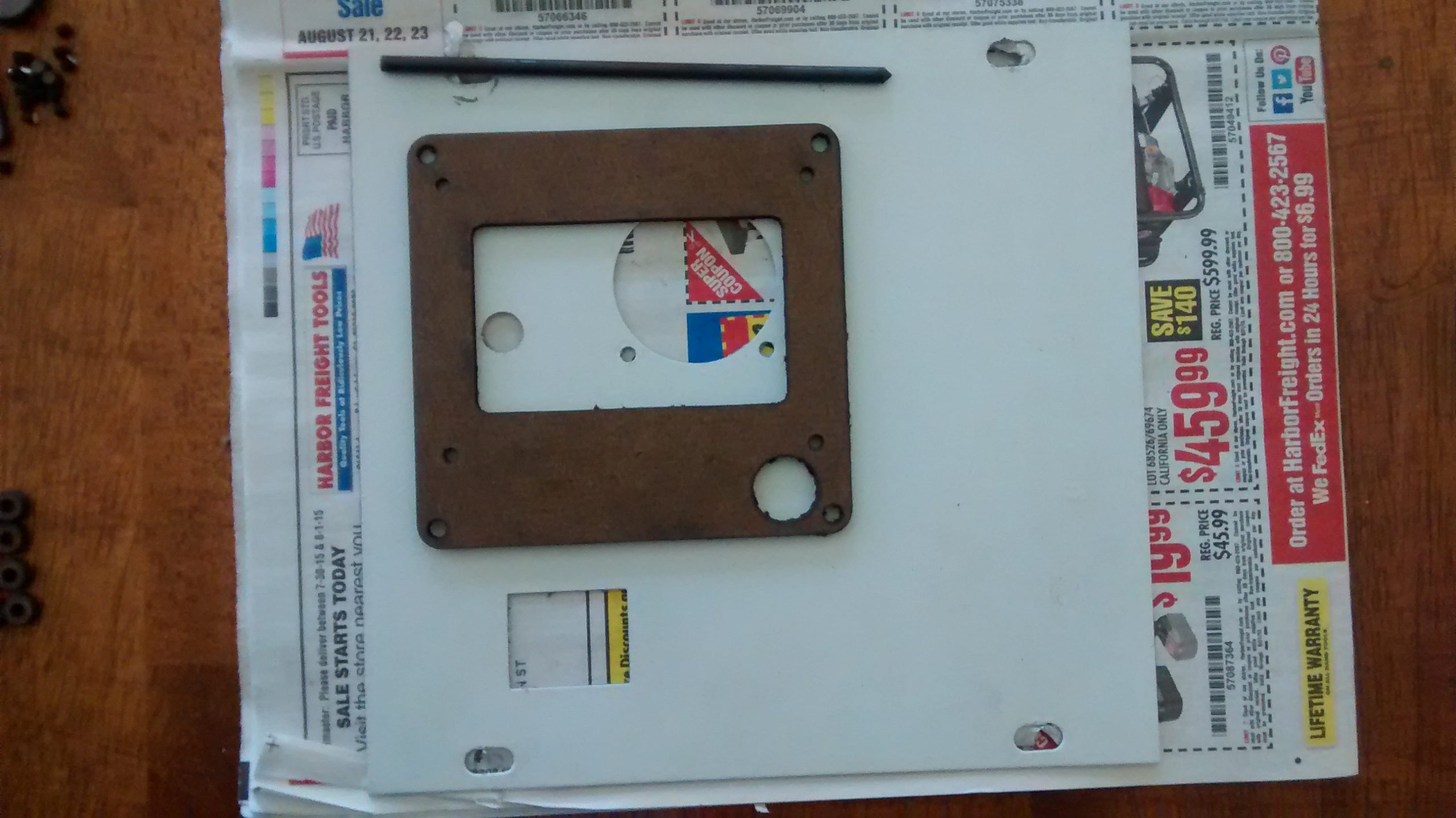
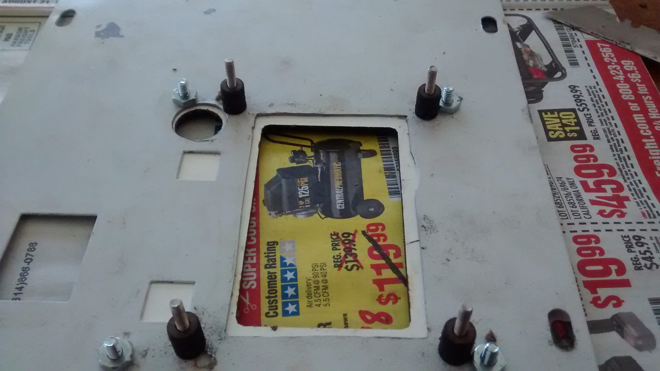
As amusing as the instructions on the panel in broken English are, I didn’t really want them there. After tearing off the sticker on the panel there was some chipped paint and a bit of adhesive that just didn’t want to come all the way off, so I just flipped it over. I placed the mounting panel were I wanted it traced the location of the LCD and marked the holes with a transfer punch.
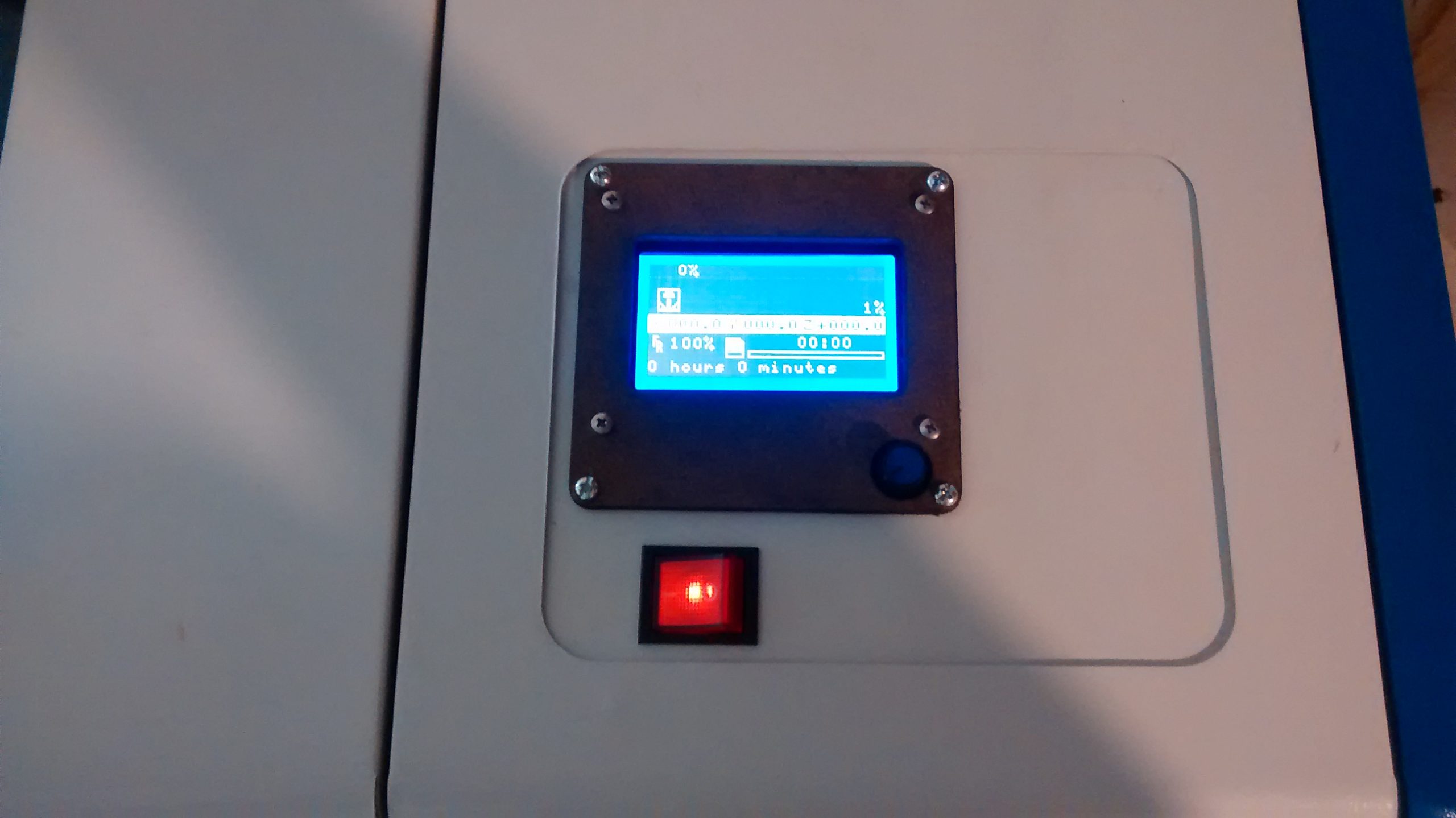
Everything bolted together nicely and looks pretty clean. The SD card is also quite easy to access on the open lid which saved a bit of effort of trying to line that up with a hole and requiring the LCD to protrude from the case more.