Samantha and I are very deliberate with our budget; it allowed us to pay off our debt including our house. You can only be so strict before it wears you out, though. So part of our budget is “blow money”. We each get money to spend on whatever we wish, no questions asked. (though legal and ethical limitations probably still apply)
We also try to be deliberate with gifts and avoid blatant consumerism. We both became annoyed at family gatherings that just seemed to be an exchange of gift cards. Generosity is also supposed to be part of our ethos, so that along with our frugality lead us to find a replacement. We’ve settled to trying to substitute the plastic stuff and gift cards with quality time (a nice dinner together) or homemade gifts (but ones that take effort, skill and time).
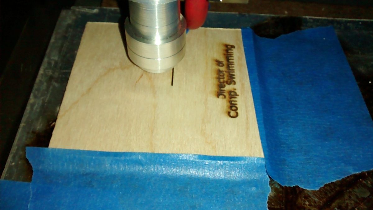
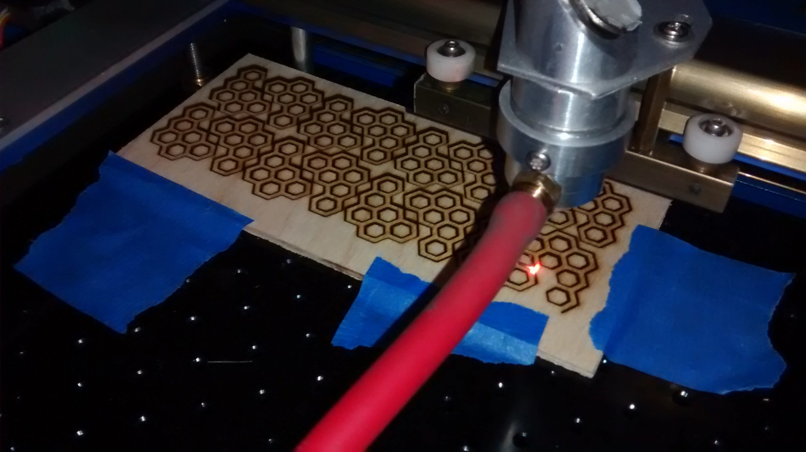
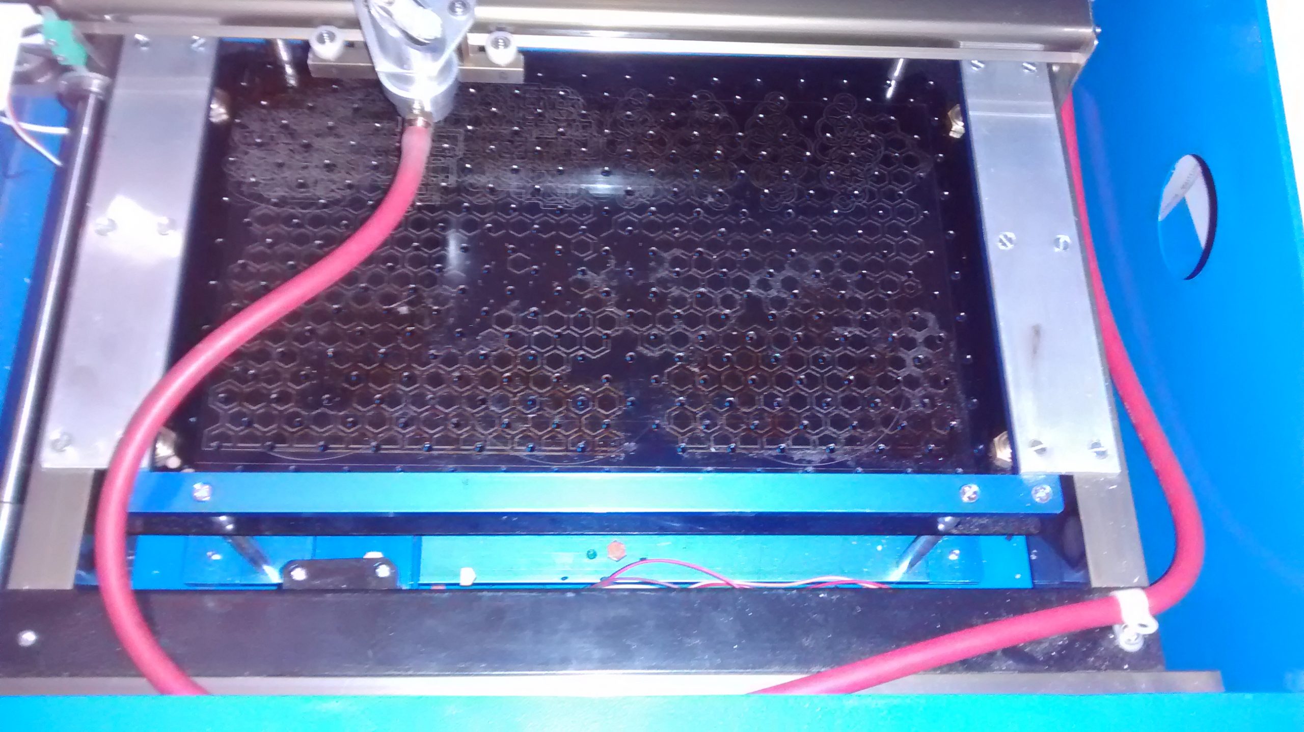
Enter my new laser. Samantha didn’t really get it. I saved up several months of my blow money to purchase it, so she didn’t care that I bought it. She did, however, ask what it was for and why I wanted it. That, of course, is the dumbest question in the world… to which I had no concise answer. Finally, it came time to think about Christmas and the answer manifested itself.
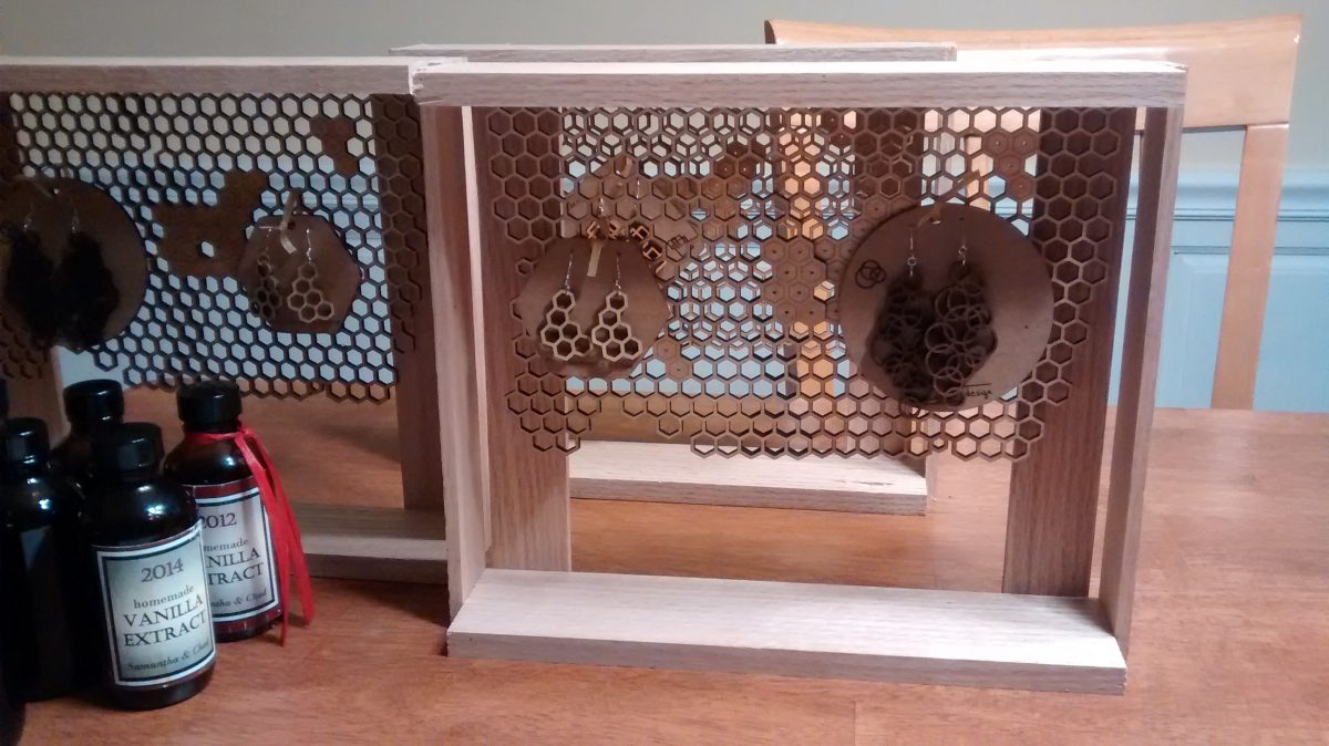
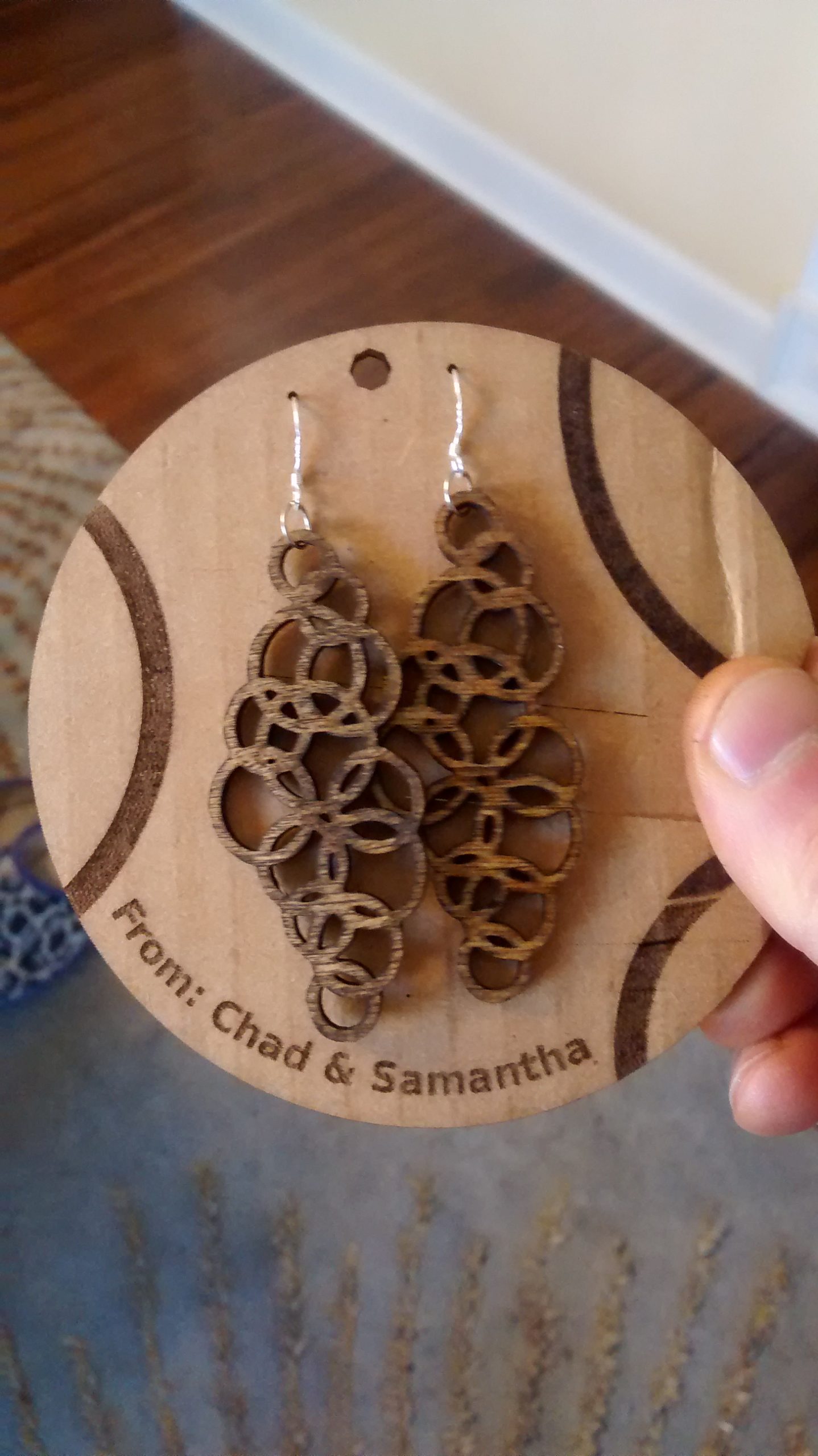
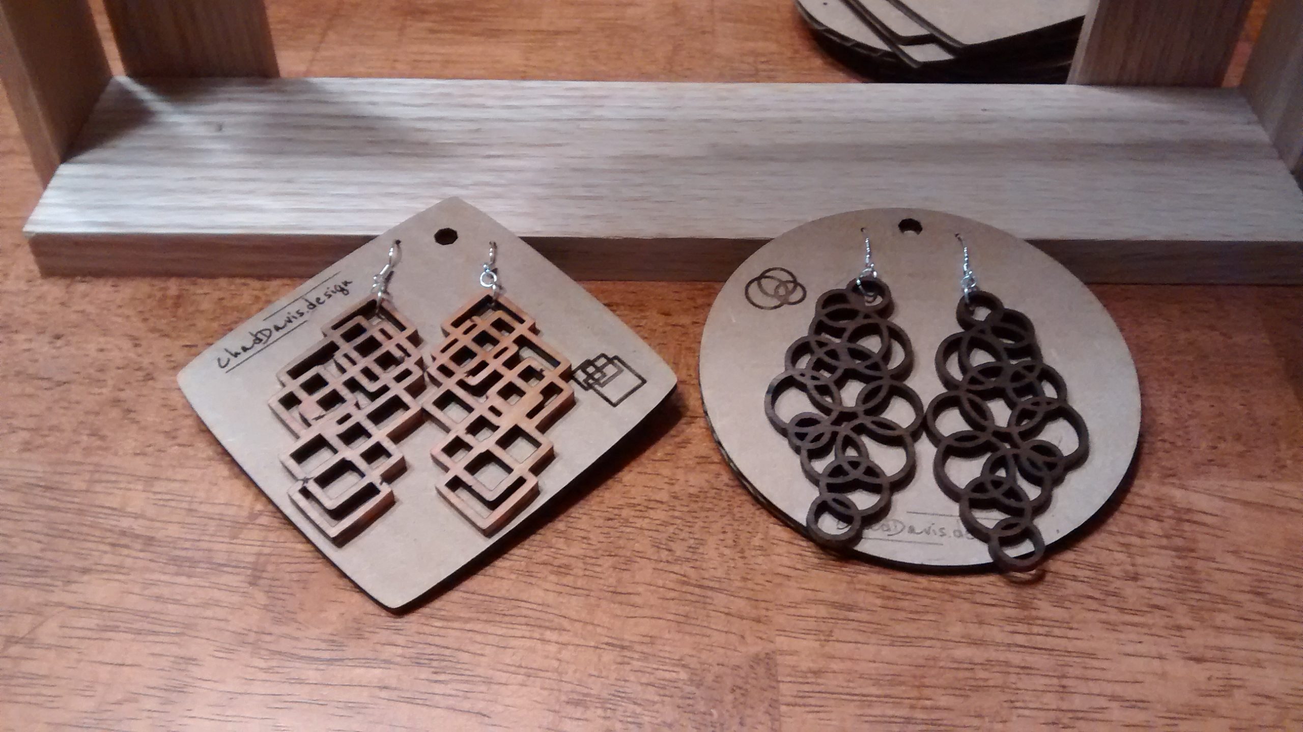
For all the women in the family, I made wooden earrings. Complete with a backing card made from scrap reclaimed corrugated cardboard. For the important women (mothers), I made honeycomb earring holders. (also pictured with the holders is the vanilla extract we’ve made for several years that is now a gift expected by a few)
They were well-liked, and more importantly to me, Samantha thinks I’m a little less crazy for wanting the laser.

 The
The 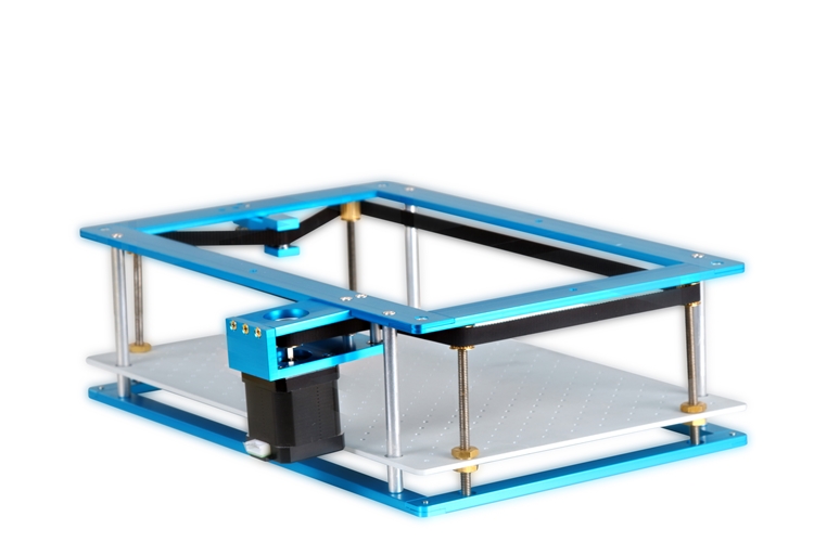
